1 4 or 1 8 imperial units us scales.
Engineering drawing scale ratio.
20 x 12 scale factor 240.
Working out the scale.
To scale a si drawing.
The difference between the ratio numbers represents the factor by which the scaled image is enlarged or reduced.
1 20 1 50 or 1 100 si units or.
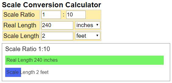
This is an online scale length converter that calculates the actual length and the scale length according to the scale ratio.
Select the desired scale.
8 1 x 12 scale factor 96.
The change between the original and the scaled drawing is generally represented by two numbers separated by a colon like 10 1 read as ten to one.
1 20 multiply the feet by 12.
To convert an architectural drawing scale to a scale factor.
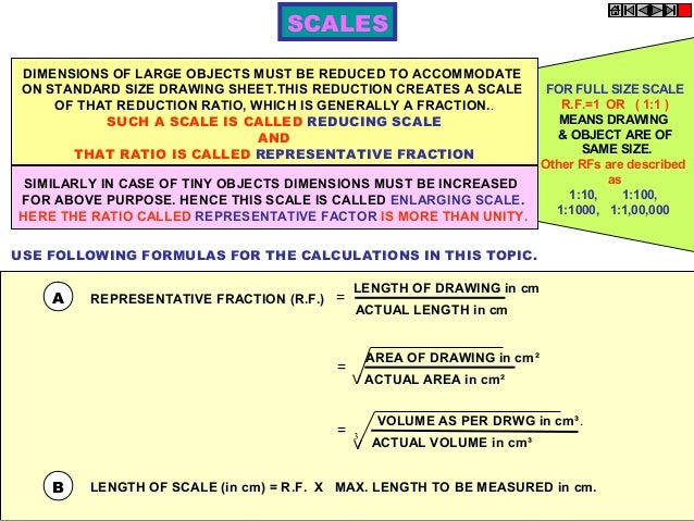
Scale drawings show an image either reduced or enlarged in size.
With visual graphic and formula it let us more easily understand the calculation process and the result.
Most of engineering students get confused about scale reduction and enlargement.
Example blueprint drawing scale 1 50.
Usually the word scale is used for an instrument used for drawing straight lines.
Where the denominator is the number after the colon.
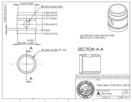
An engineering drawing is a type of technical drawing that is used to convey information about an object.
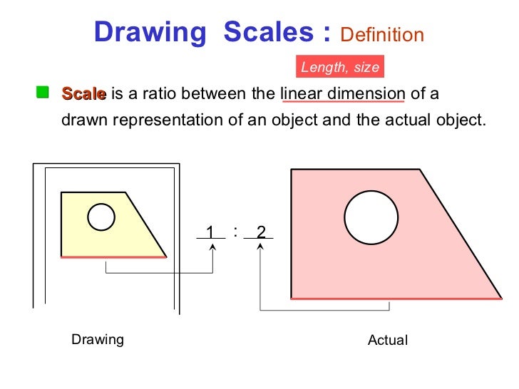
A scale is shown as a ratio for example 1 100.
The ratio and decimal numbers can be helpful if you are working in paper space and need to know what the scale factors are for window resizing in order to create the proper scale.
A drawing at a scale of 1 100 means that the object is 100 times smaller than in real life scale 1 1.
Multiply the measurement on the drawing with the denominator.
1 8 1 0 invert the fraction and multiply by 12.
In the past prints were plotted on a plotter to exact scale ratios and the user could know that a line on the drawing 15mm long corresponded to a 30mm part dimension because the drawing said 1 2 in the scale box of the title block.
To convert an engineering drawing scale to a scale factor.
Select the desired scale.
Blueprint drawings are typically drawn in.
Scale the original border down by this amount and your scale is changed.
Scale ratio could be set by yourself supports different length units including imperial units and metric units.
Scale is the ratio of the linear dimension of an element of an object as represented in the drawing to the real linear dimension of the same element of the object itself.
A scale ruler is a tool for measuring lengths and transferring measurements at a fixed ratio of length.
Aaa drafting using a scale to read an engineering drawing.